
HEART-LUNG MACHINES – SOME THOUGHTS ABOUT PUMP CONFIGURATION AND DESIGN.
By Collin Green
Colin G. Green, Copenhagen, Denmark. ([email protected])
I was recently chatting with an overseas perfusionist who sent me a photo of his pediatric CPB circuit set-up. He was particularly pleased with his low priming volume which was due to thoughtful design and tubing positioning: He positioned his venous/cardiotomy reservoir close to the table and about 20 cm lower than the patient’s right atrium giving him a relatively short venous line. He applied a touch of vacuum to the reservoir to assist his venous drainage. So everything looked good apart from his long sucker lines, both from the patient to the pumps and especially from the pumps to the higher reservoir, and his longer reservoir outlet to pump and oxygenator, and arterial line from pump to patient.. His machine was a conventional “4 in a row” modular pump configuration.
This started a discussion’ initiated by myself, on the merits and de-merits of conventional horizontal “3/4/5 in a row” modular pump machines. Admittedly there are machines today where the arterial pump can be re-positioned closer to the table and sometimes higher but to the best of my knowledge sucker and cardioplegia pumps tend to stay on the machine base. We both agreed that in principal it would be advantageous to have multi-positionable pumps to allow even more optimal circuit design . As far as I know there have only been two machines in recent years that have had multi-pump positioning flexibility – the Maquet HL 30 and the Medtronic Performer.
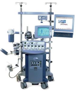
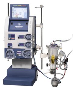
Neither of these seem to have caught on and there could be many reasons for this , both technically and commercially. The thought has crossed my mind that maybe they were too unconventional perhaps confirming that perfusionists generally are traditionalists and don’t like change. However they both allowed sucker lines to come in straight from the table and the oxygenator and arterial pump to be positioned higher in relation to patient and table. Maybe they weren’t that popular because they were primarily “stand-up and run” machines ! Todays perfusionists are used to sitting comfortably even though this means bending and stretching to access circuit components and hardware.
Now if we look back into history it’s interesting to note that the early machines from the late 1950’s did not have modular blood pumps. It was before their time. In fact the machine that performed the first successful cardiopulmonary bypass in 1953, the Gibbon machine, was a “stand-up and run” machine with pumps and oxygenator on the top surface. Below are examples of 4 machines from that period.
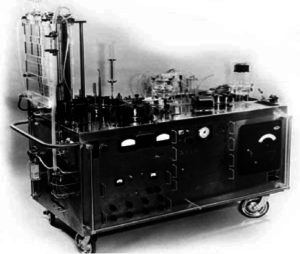
The first two are pictured above and on the left is the Gibbon Mark 2 machine with the vertical screen oxygenator. On the right is the machine as modified by Dr John Kirklin at the Mayo Clinic.
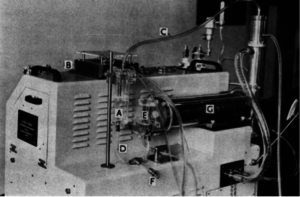
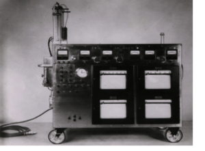
Above is the Guys-Ross machine with a Kay-Cross rotating disc oxygenator (C) with a venous reservoir (E). The arterial pump was on the side beneath the vertical stainless heat exchanger. There was one suction pump (B) on the top surface with a suction chamber (A). I did my first perfusions at Guys Hospital in London, England with this machine in 1962. Venous drainage was by gravity, no vacuum , into the venous reservoir. There was a drainage height of about 30 cm with generally no drainage problems.
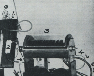
Interestingly the Kay-Cross disc oxygenator was inspired by an early disc oxygenator developed by Dr. Viking Bjoerk in Stockholm, Sweden in 1948. Below is this oxygenator which consisted of forty 13 cm diameter stainless discs in groups of 4 that oxygenated blood flows of up to 1100 ml/min. Dr. Bjoerk used this oxygenator for cerebral perfusion during occlusion of the vena cavae.
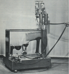
The Kay-Cross oxygenator was made in Cleveland, Ohio by Pemco Inc. and below is a photo of another “stand up and run” machine. This one made by Pemco with the disc oxygenator.
Again, oxygenator, pumps and heat exchanger on top of the machine at table level.
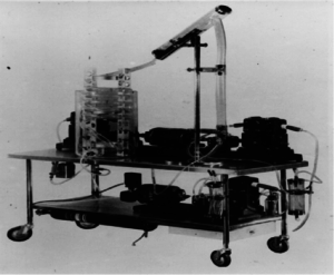
Lastly, one more “stand-up and run” machine. This time made in Copenhagen, Denmark by Polystan. This machine was designed to be used with one of the first disposable, pre-sterilzed bubble oxygenators, also made by Polystan. The first clinical with this machine was in Copenhagen on the 22nd of February 1957.
The arterial pump was on the left-hand side on top of the base cabinet. There were 3 vacuum chambers for 3 individual sucker lines. Vacuum to these chambers was supplied from a vacuum pump in the machine base and the amount of vacuum was controllable for each chamber. If you look carefully you’ll see a butchers scale at the back of the machine. This constantly weighed the oxygenator displaying its weight. A very simple and effective means of seeing and measuring volume changes in the oxygenator. The machine was placed at right-angles to the table with short sucker and venous lines .For those of you who have not seen this bubbler before, venous and suction blood entered the vertical column on the right into which oxygen bubbles were introduced. At the top of the column the blood entered and flowed horizonatally into and through an antifoam coated defoamer. The blood then flowed into and through two inverted U-shaped bubble traps with pocket filters finally entering the left-hand vertical outlet section. The arterial reservoir section was collapsible so that gross air could not leave the oxygenator should the reservoir empty. The walls collapsed.
The following is probably the most iconic and important machine and oxygenator configuration ever produced and used. Not because of its elegance or its engineering but because it was responsible for the implementation of open heart surgery with cardiopulmonary bypass worldwide. I am of course referring to the Lillehei-DeWall machine and oxygenator, another “stand-up and run” machine.
The bubble oxygenator, above left on top of the trolley, was made from three lengths of tubing – the vertical bubble column, slanting defoaming chamber and helix arterial reservoir that was positioned in a water bath. These tubing lengths were disposable and new lengths were used for each perfusion. Venous drainage was by gravity into a reservoir chamber from which a Sigmamotor pump pumped the blood to the bottom of the bubble column. Suction was vacuum assisted into a separate reservoir chamber positioned close to the floor. A second Sigmamotor pump transferred this blood to the bottom of the bubble column into which oxygen bubbles were introduced. The oxygenated blood then passed into the defoaming section and helix arterial reservoir where a third Sigmamotor pump transferred the arterialized blood to the patient. The first clinicals at the University of Minnesota were done in 1956. The oxygenator was further developed into a disposable, pre-sterilized sheet oxygenator which became available from Travenol Laboratories in 1957. At about the same time a machine with some of the earliest modular pumps was produced by Sarns in Ann Arbor.
So far so good. We can conclude that, with the exception of the Polystan machine from 1957, modular pumps first became available and in use on pump bases with the introduction of disposable commercial bubble oxygenators. At the same time gravity venous drainage became the standard,with the disposable bubblers having their venous inlets close to floor level. It’s interesting to note that between about 1960 and 1980 an estimated 25 to 30 commercial, disposable, pre-sterilized bubble oxygenators became available, all of which had venous inlets close to floor level. I forgot to mention that with these commercial bubblers, a separate cardiotomy reservoir was needed into which suction blood was pumped before leaving by gravity to the bubble column. This reservoir was usually positioned a little higher than the bubbler.
With todays almost total use worldwide of membrane oxygenators with integrated venous/cardiotomy reservoirs, there seems to be no need for large patient /reservoir drainage heights.especially as VAVD solutions are available. In my opinon there are many clinical and practical advantages in positioning reservoirs both higher and closer to the table. To take full advantage of this possibility all pumps need to be positioned higher and correctly in relation to their function. This is particularly true for sucker pumps as suction is known to be the main source of blood trauma during CPB.
So, I ask you all why aren’t more machine produced and used with multi-positional pumps ? Why does industry continue building conventional machines with “3/4/5 in a row” modular pumps on a base.? Why do todays perfusionists continue to accept this configuration?
NOTE: Some of the images used in this blog, are from my presentation given to the American Academy of Cardiovascular Perfusion (theaacp.com) meeting in Savannah on February 6 this year.
Colin G. Green, Copenhagen, Denmark. ([email protected])


